
General Building Tips



Cutting Out Printed Wood Parts
by Allan P. WeismanHere is a tip about cutting out small parts that might crack into tiny hard to reglue pieces, such as the small fingers of balsa wood left after cutting out stringer slots. Before cutting use rubber cement to paste some heavy Kraft paper on the back of the printed wood. The Kraft paper will hold all the little pieces in place since the paper has no grain to split. Then later on if there is a split in the wood rub a very thin layer of rubber cement over the front of the split part after cutting. When the cement is dry, peal the paper off the back of the wood, and gently rub with your finger to remove the rubber cement residue. This adds very little weight to the model, but a lot of extra strength.
Trace the parts on the printed wood prior to cutting them out, in this way you will have a pattern for a Extra part should you make a cutting error. Another easy way to do this would be to photocopy the printed wood to make your patterns.
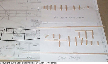
While you are cutting all the fuselage pieces out, some pieces can get lost or destroyed, but fortunately there is a way to keep all the little pieces of strip wood safe from getting lost and in some semblance of order. All that is needed is a sheet of paper, and a roll of double sided tape. Hold the paper sideways, then put a strip of tape across the page near the bottom. You can stick your fuselage-bottom longerons on this strip. Now tape another strip a little farther up the piece of paper, on this you can put the extra uprights from the cabin area. Make another strip for the top-longerons, and then one final strip for the top and bottom cross pieces. Now you have all the strip wood pieces safe from getting lost. If you put them on in order to build the model it makes things a lot easier. This same system can be used anywhere you cut parts prior to construction.
Sanding
Get some spruce sticks of various thicknesses, 1/16, 3/32, 1/8, 3/8, etc. Cut the sticks into 6" lengths then glue different grades of sand paper on the edges of the sticks. You now have a set of sander blocks to use on the inside of stringer slots. Sanding blocks can also be made by gluing sand paper to various sized dowels and lumber trim shapes such as half round, quarter round etc. for sanding hard to reach places like the formers between stringers.
Inexpensive sanding sticks can be bought at the local cosmetic department of any of the chain stores. They are inexpensive, can be cut to any shape and come in different grits. The clerk will probably know them as emery boards or nail files. - Dick LeClair
Building Methods
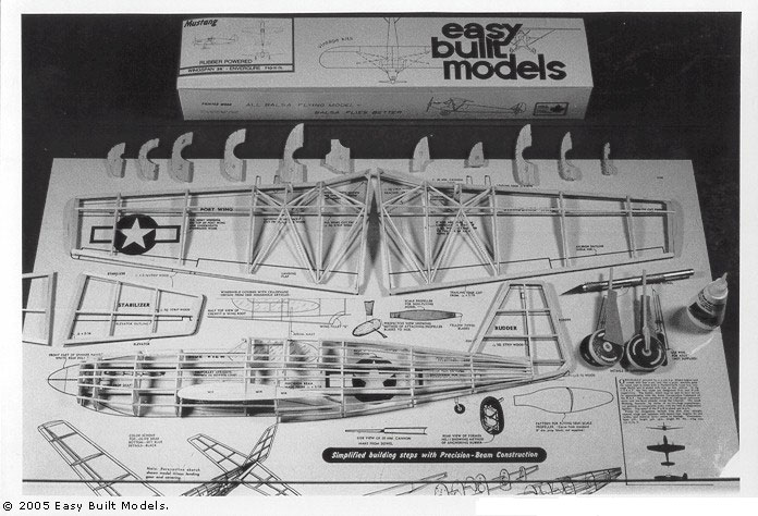
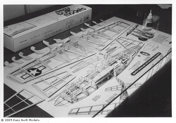
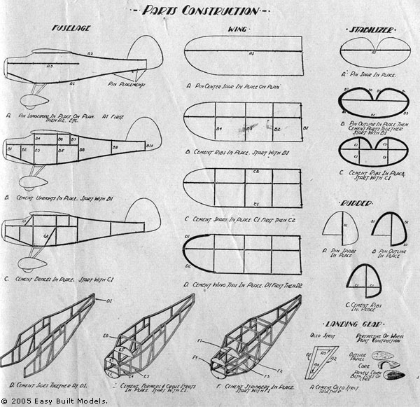
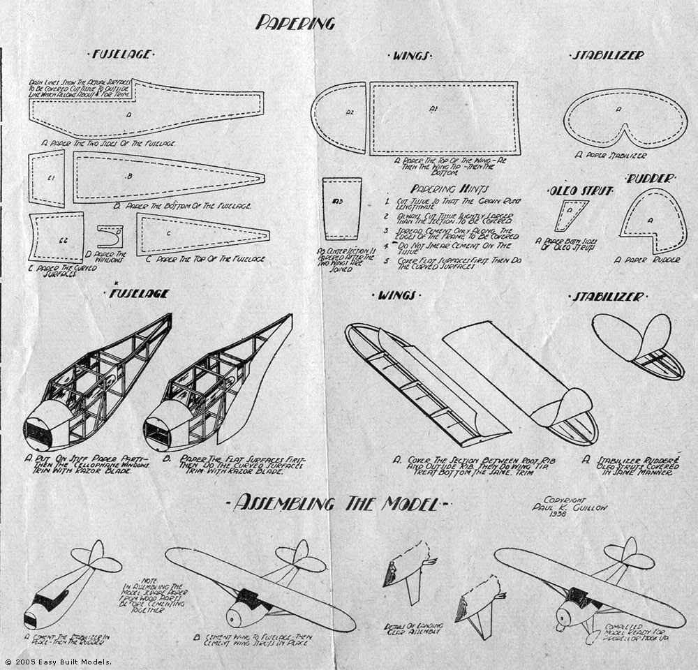
When building a half shell fuselage usually only one side view is shown on the plan. One side is built over the plan, and the other side is built on the first side this can cause a lot of misalignment when gluing the very small areas of the left, and right formers together. These problems can be avoided very easily. The steps to do this are simple.
1) Make a duplicate set of center pieces that the half formers are glued to.
2) If necessary enlarge the notch in the half former that goes over the center pieces.
3) Build one half of the fuselage as usual using a triangle to insure that the half formers are trued up at a proper 90 degree angle to the building board.
4) Turn plan over, and rub a light coating of cooking oil over the back of the plan in the area of the fuselage side view. This will make the plan translucent so that the other half can be built directly over the plan as the first half was.
5) Glue the 2 sides together along the wide center pieces this gives you a large glue area, and you can use V notched wood, or spring clothes pins to hold the 2 halves together as the glue dries.
Allan P. Weisman
I build all models on a plate of glass, such as that used for a picture, or one cut by a shop. I put the plan underneath the glass. The model is then built as normal on top of the glass, and the pieces held in place with masking tape. This ensures all parts and components are perfectly flat, as well as providing a better work area. Excess glue, paint, and other droppings are easily cleaned with a razor blade or Windex. - Rick Krakoff
Here is another way to build both sides of half shell fuselages over the plan. Most models of this type build with a right side, and a left side. one side is built over the plan, the other is built in the air, which means one side can be perfectly aligned, the other might be built with warps. There are some models such as the Easy Built Gremlin which are built as top, and bottom. This type of construction allows you to build both halves over the plans. Converting the side built to top, and bottom built is not difficult. Simply glue the half formers together on a flat surface. Then locate the center side stringer notch (one that goes from nose to tail). Cut the formers apart across the center of this notch, enlarge the notch to take a full stringer in both halves. Now you can build the top half over the plan top view, using triangles to keep everything properly aligned. When it is dry, take it off the plan, and build the bottom half over the top view, using triangles to keep proper alignment. The completed halves can now be joined, completing the construction. If you need small building triangles, take a strip of balsa 1/4" thick, and 1" wide, now use a miter box and razor saw to cut out as many triangles as you need. They can be pinned to your building board where needed.
It should be noted that this technique will make the model slightly heavier but may make it easier for some builders to get that straight and true fuselage. - Allan P. Weisman
When adding wheels to the landing gear wire, you will need to use retainers to keep them from falling off. The usual choices are:
A) Wrap soft wire around the landing gear wire and fix with solder. This adds weight, and may imbalance the model causing unwanted turns in flight.
B) Wrap heavy thread around the landing gear wire and fix with glue. This adds less weight than wire, but may also cause imbalance. C) Build up a layer of glue on the ends of the landing gear wire. Unless exactly the same weight of glue is used on both sides, imbalance may occur.
D) Bend the ends of the landing gear wire. This does not affect in any way but one, it doesn't look good esthetically.
Here is a great no-cost alternative wheel retainer that adds very little weight, causes no imbalance, and is virtually invisible. There is always a bit of celluloid left over after cutting out the window patterns for a model (other plastics can be used as well), use a paper hole puncher to easily make small round, invisible retainers of equal size. Now use a pin to make a hole that is less than the diameter of the landing gear wire in each of the retainers. All that remains is simply to force the plastic onto the ends of the wire. Friction will hold the plastic retainers in place, and they are invisible. - Allan P. Weisman
De-Thermalizer - The simplest way to deal with a kick-up stab DT, would be to extend the fuselage back to the rear edge of the rudder, then build a subrudder to match the plan, and let the stab with upper portion of the rudder attached rest on the top of the fuselage. On my Miss Canada Senior, I ended the fuselage where the plan shows and after building the rudder per the plan, I simply cut it in two pieces on a line level with the bottom of the stab line, added a couple of reinforcements on each side of the cut, glued the upper rudder portion to the stab and the lower portion to the bottom of the fuselage extending aft as shown on the plan. You'll need some better support than shown on the plan for the sub-rudder. I also widened the fuselage about 1/8" at the point where the rear motor is located to make a blast tube easier to insert. - George White
Gang Cutting Ribs from Template
Wood Putty for Balsa
Tools for the Model Builder
Here is a picture of the basic tools required to build the framework of a model. Please note that the items shown are a representative. In other words the X-Acto Jr. knife shown might just as well be a #1 knife, and the saw shown might be a coping saw. This picture is merely to give the new modeler an idea of what is needed.
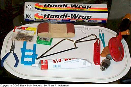
The items shown are:
PLASTIC WRAP: To cover and protect plans.
T-PINS: To pin parts down.
SANDING BLOCK: For clean up work, final shaping of nose block, and preparing for finishing.
PUSH PINS: To pin plan and plastic wrap to building board.
RAZOR BLADES: For cutting wood in straight lines.
SAW: For rough shaping of nose blocks.
TWEEZERS: For handling small parts.
MODELING KNIFE: For cutting curved surfaces.
HAND DRILL: For drilling out hole in nose block for prop bearing.
PLIERS: For shaping landing gear wire.
CLAMPS: For holding parts together while glue dries.
GLUE: For gluing parts together.
- Allan P. Weisman
Socks for your Tissue Iron